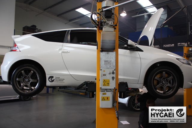
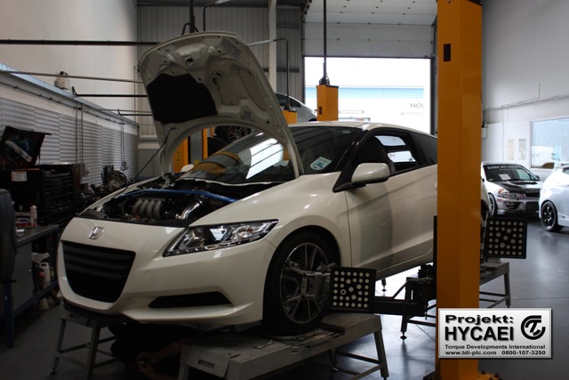
Honda CR-Z – Turbocharger Installation
As part of the on-going plans for Projekt HYCAEI include a turbocharger package, it’s essential that the standard Honda pistons and connecting rods are replaced with heavy duty components in order to withstand the increased cylinder pressures. While the engine is apart we investigate the flow characteristics of the cylinder head in order to improve the internal aerodynamics and increase volumetric efficiency.
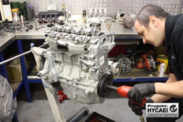
The first task on the job list is to remove the engine. This is the first time that we’ve ventured inside the CR-Z engine so we’re really looking forward to learning more about it.
Engine Removal
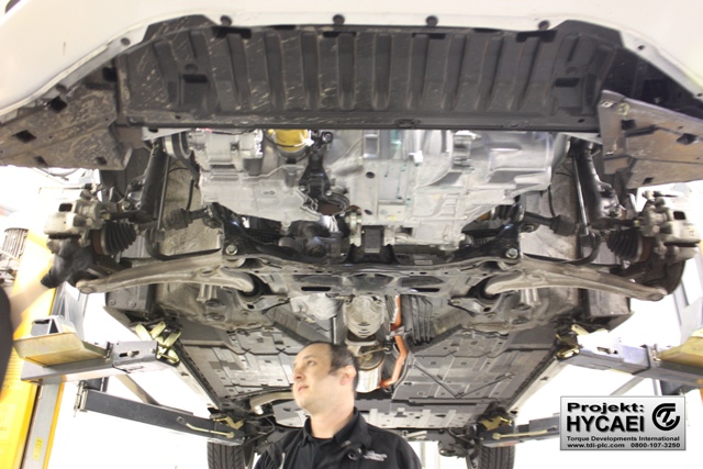
Engine Removal
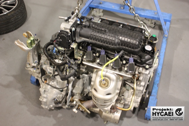
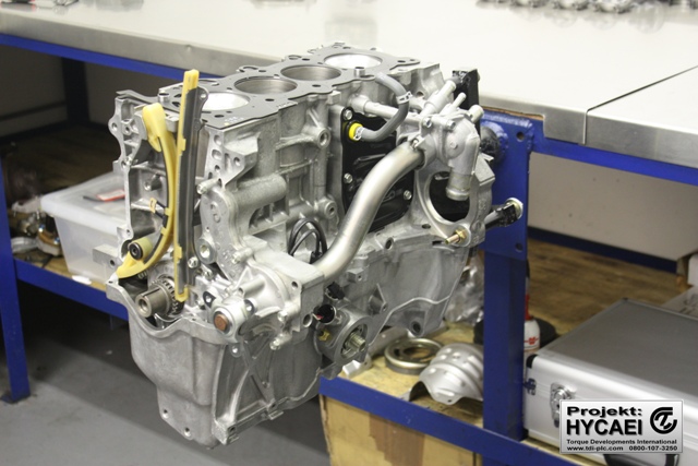
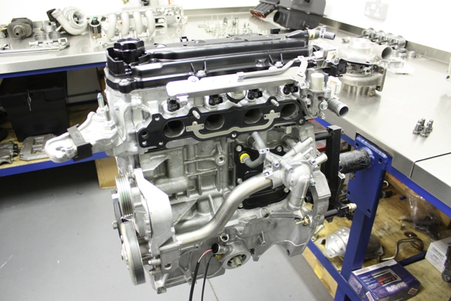
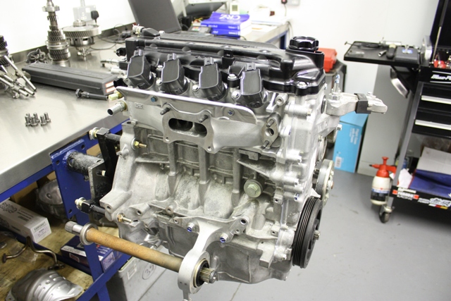
Engine Removed
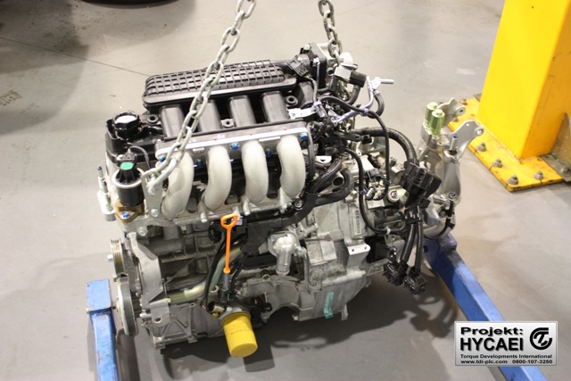
Engine Removed
Engine Removed
The heart of the CR-Z…
Modern car manufacturers are constantly looking for ways to make their vehicle more fuel efficient and better for the environment. Whilst the average petrol head doesn’t give two hoots about the environment (and is only concerned about how much their VTEC goes BWWAAAHHHHH), their are goods reasons for it.
Honda developed what they call their IMA system. This stands for ‘Integrated Motor Assist’ and is an electric motor which offers an additional 20bhp over what the engine can produce. Whilst 20bhp doesn’t sound like alot, it’s important to remember that this additional power is always working away in the background, providing that extra push to get the vehicle down the road.
As long as the IMA unit is pushing, the petrol engine doesn’t have to work quite as hard, therefore reducing the engine effort and less effort means less fuel used. Before you know it, you’ve achieved 50mpg and drastically reduced fuel bill and running costs to boot!
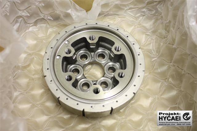
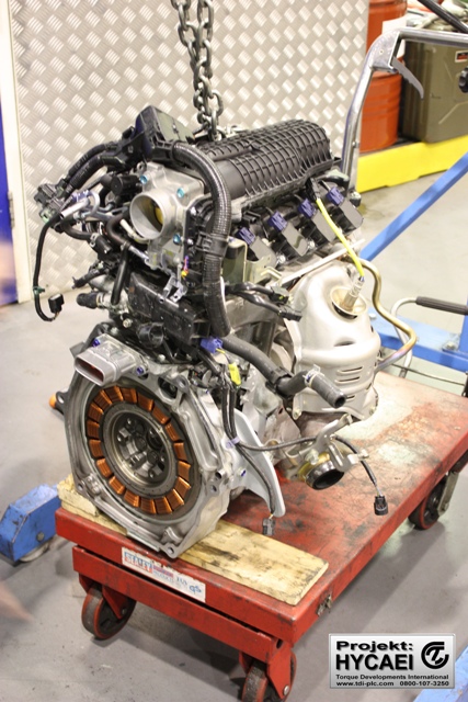
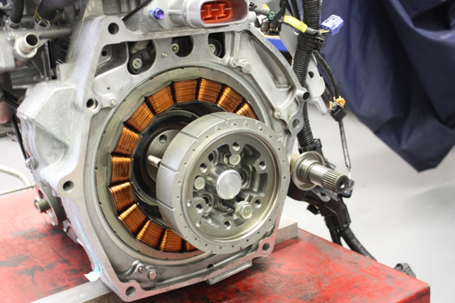
This is the rotor unit that spins inside the stator unit. It’s this movement that generates the additional power. You can see that it bolts to the end of the crankshaft just like a traditional flywheel. The actual flywheel bolts to the stator using the outer ring of threaded holes.
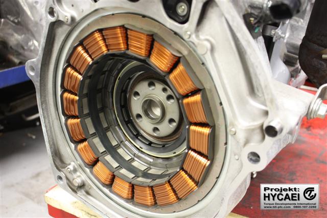
The stator unit bolts to the engine block just like a gearbox bell housing would. The magnets, housed around the outside of the unit are very powerful and a special tool was supplied by our friends at Honda. When removing the rotor, the special tool ensured that at no point does the stator get too close to the magnets. Needless to say, our workshop staff were very cautious when removing it.
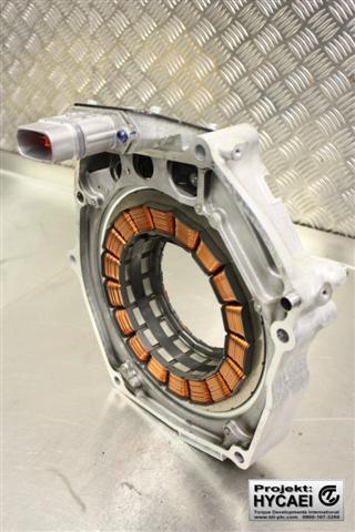
Here is the unit removed from the engine block. Because of the delicate nature of the IMA unit, the whole assembly will be stored separately and away from metallic objects for the duration of the project build.
Following a painless engine extraction, we get on with stripping it down to it’s core components to get it ready for the heavy duty upgrades.
Engine Strip
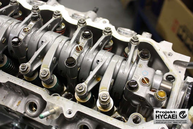
The camshaft and rocker becomes exposed.
Here, the camshaft and rocker become exposed. You can see that this particular engine only runs one camshaft (or SOHC as it’s usually refereed to) but it still runs a variable cam system but not in the conventional VTEC sense.
Basically, when the engine isn’t in it’s VTEC operation, it only operates 1 of the 2 intake valves and both of the exhaust valves. This creates a swirling effect in the cylinder to give you your economy.
When the engine goes into it’s VTEC operation, both of the intake valves engage, turning the swirling effect into a barrel roll effect. This is less beneficial for economy and more suited to power.
The swirling effect allows for lean mixtures to be used without misfires…. where as the barrel roll pattern gives the best charge air mixing, which is great for detonation resistance at full throttle. Perfect for what we’ve got in mind.
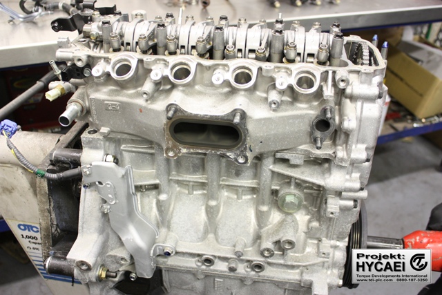
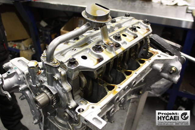
We can immediately see the unusual design of cylinder head that joins all of the exhaust ports together into a common port. This looks like a challenge from a flow perspective!
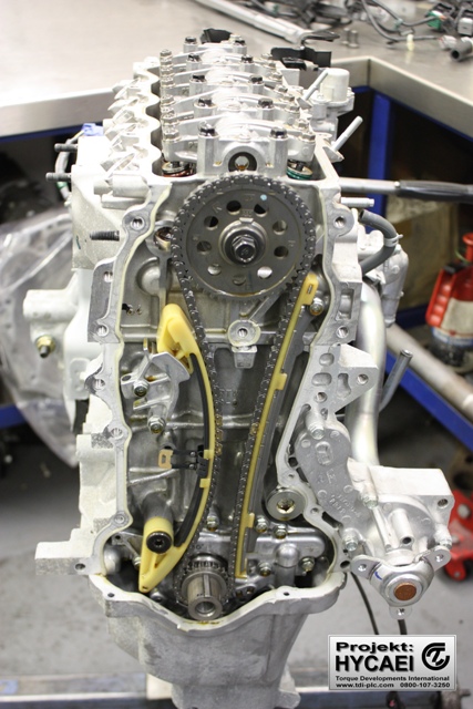
Camshaft gear and timing chain exposed.
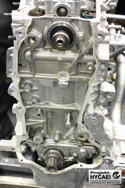
Oil pump
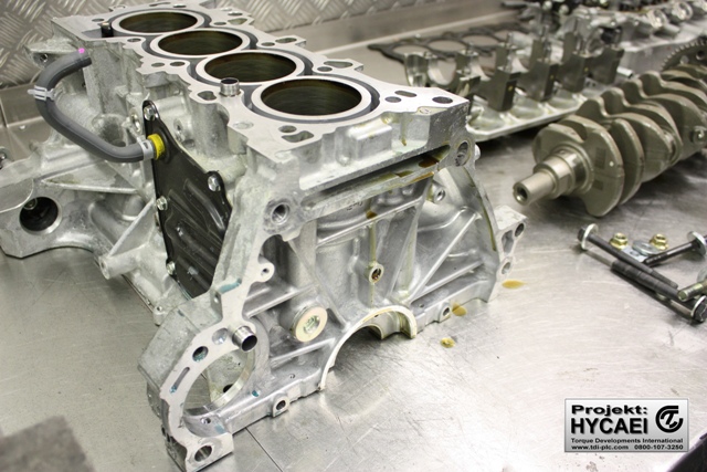
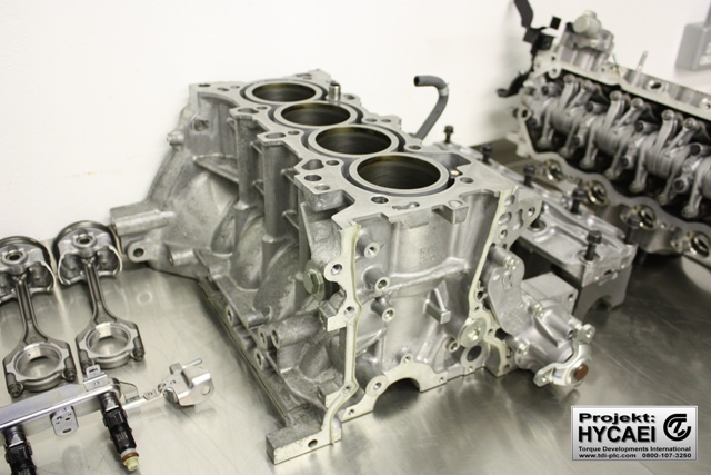
After the cylinder head is removed, the piston crowns can be seen. It all seems to be in very good shape!
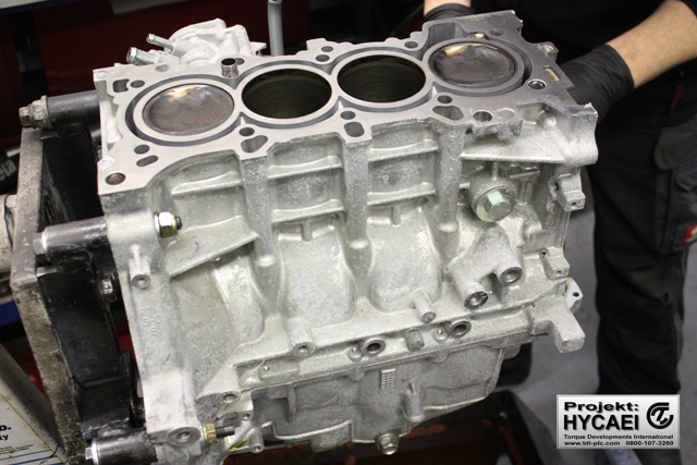
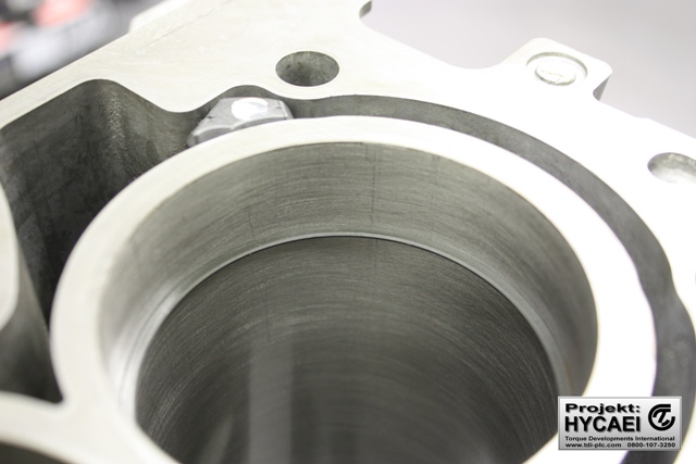
Short block
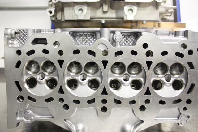
The cylinder head combustion chamber design is quite unusual with widely separated exhaust ports and i-VTEC intake arrangement. You can see in the below image that on the second cylinder, one intake port is partially open whilst the intake port next to it remains closed. This illustrates how the ‘off VTEC’ cam system works.
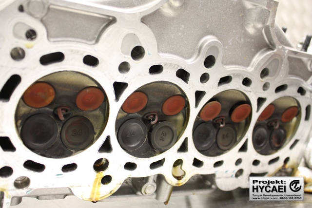
Cylinder head combustion chambers
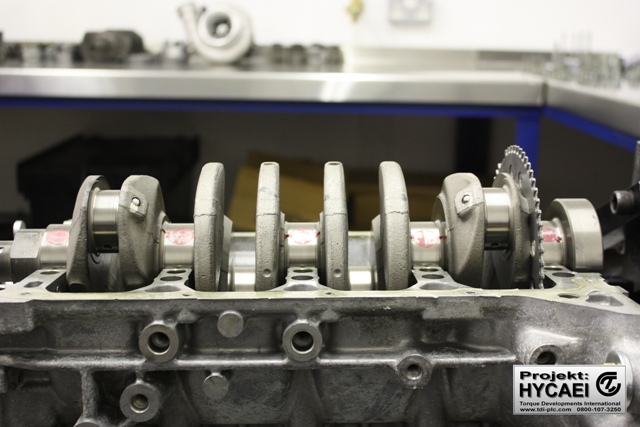
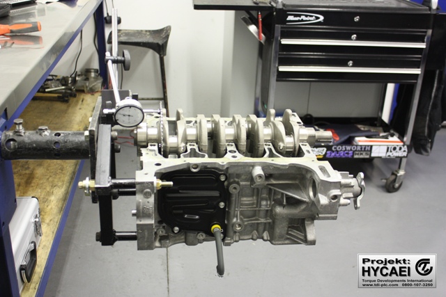
Once the sump is removed it comforting to find a robust main cap girdle to stop unwanted movement at high RPM!
Rotating Assembly
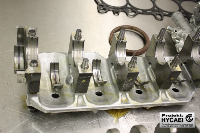
Crankshaft Main Caps and Stud Girdle
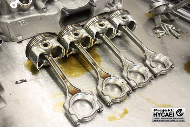
It’s quite surprising at how thin the connecting rods are. We’re sure that they won’t endure high cylinder pressures! We like the length of the rods though as that offers a good rod length to stroke ratio which improves the rod angularity which makes the engine smoother and reduces the piston speed.
The engine is now fully disassembled!
Cylinder block and crankshaft disassembled.
Now comes the interesting bit! Engine development and building are part of our competancies and something we really enjoy, so we relished the thought of getting involved with a new engine. Being very concerned about the integrity of the connecting rods and pistons we sourced a set of HKS uprated rods which are made from forged steel and wider with high tensile bolts, and forged aluminium pistons which we know to be good for approximately 300hp.
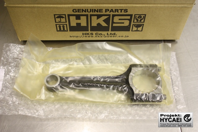
HKS forged steel connecting rod
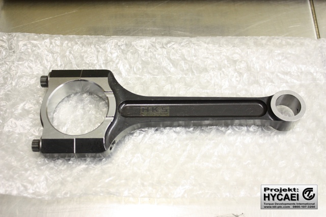
HKS forged steel connecting rod
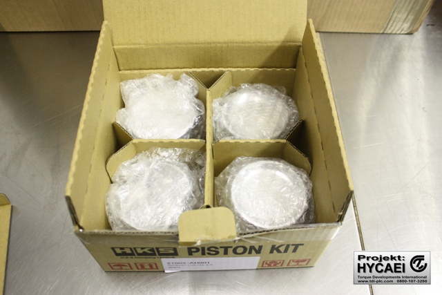
HKS forged aluminium pistons
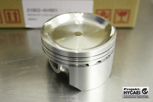
HKS forged aluminium racing piston
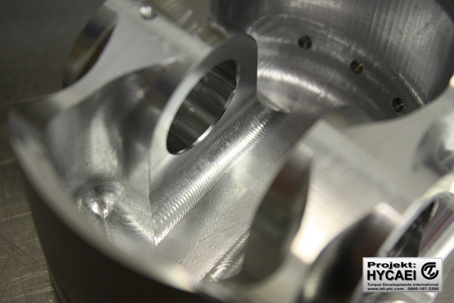
Underside of HKS forged piston
Quite unusually, the HKS piston and connecting rods have to be pressed together using a special tool on a hydraulic press. Conventionally, the normal method is either to use a lubricated fully floating bush for the piston pin to run in, or to heat the rod until the small end expands then easily push the pin in until the the rod cools down and grips the pin (known as an “interferance fit).
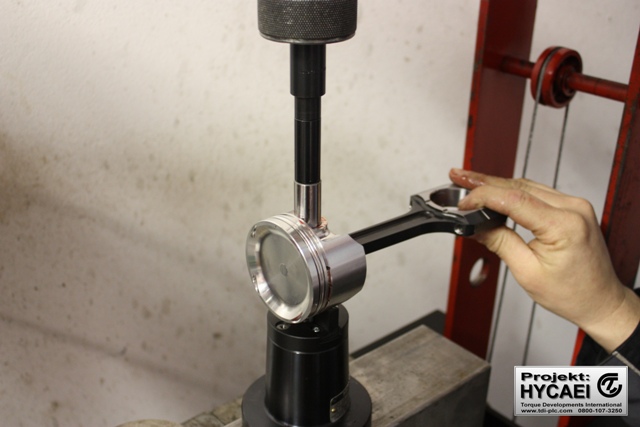
Cold press fitting the HKS pistons to the connecting rods
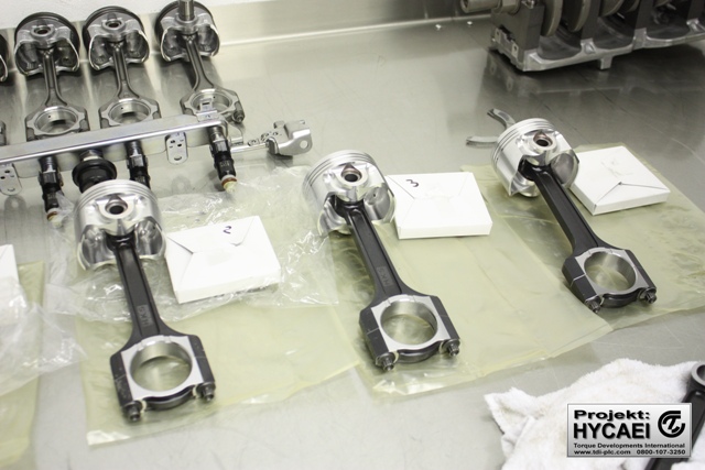
Here the HKS pistons and connecting rods are assembled. You can see the difference in thickness between the standard rods in the back ground!
Part of the engine assembly processes is to check ever single clearance as you can’t assume that everyting is correct. Here’s we checking and adjusting the piston ring gaps.
Checking the HKS piston ring gaps
We give the crankshaft the very tiniest of micro-polishes in a lathe.
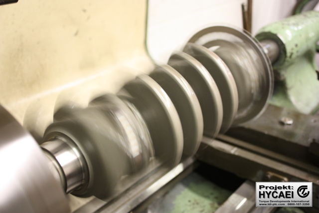
Micro polishing the crankshaft
The crankshaft main bearing and rod bearing journal clearances are checked with Plastiguage to ensure that they are not too large or small, as too large will reduce the oil pressure, and too small may cause a seizure!
Bearing clearnaces being checked
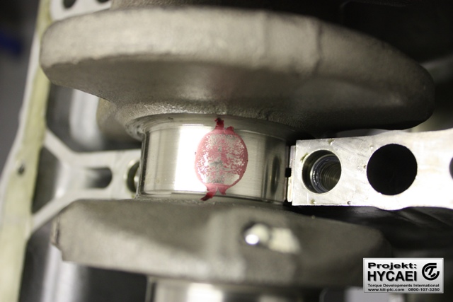
Bearing clearances being checked
The crankshaft end float is also checked.
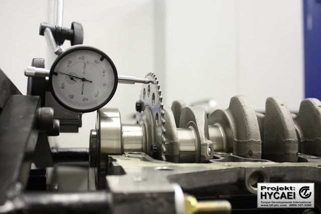
Crankshaft end float being checked.
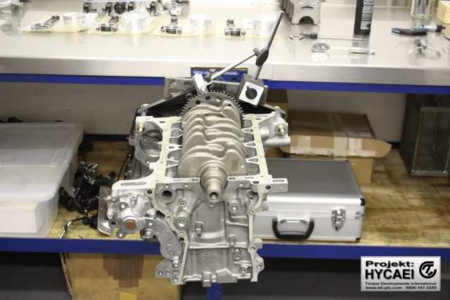
When the crankshaft bearings clearances have been checked and adjusted, the main caps and stud girdle can be installed and torqued down.
Main bearing caps and girdle installed
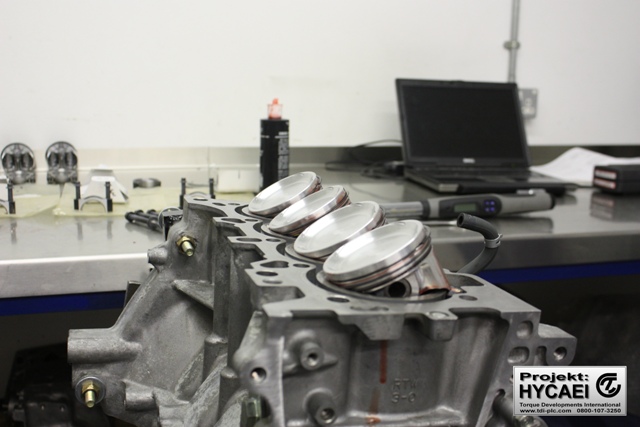
Once the piston ring gaps have been checked and adjusted they can be fitted to the pistons, then the HKS piston/rod assemblies can be installed in the cylinder block.
With the elevated cylinder pressures that we’re anticipating, the OEM cylinder head gasket would be a weak point so we’ve used an HKS multi layer metal head gasket which we know will do the job! They are available in 0.8mm and 1.2mm thicknesses.
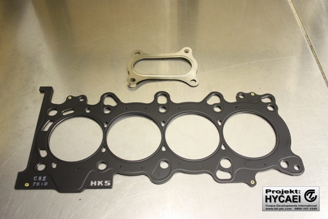
HKS metal head gasket
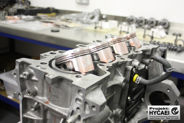
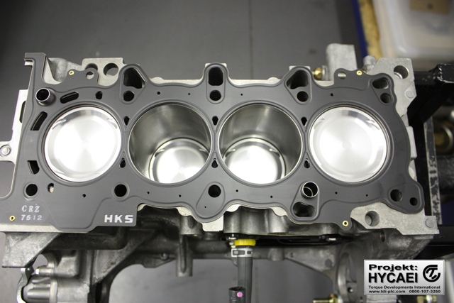
The HKS metal head gasket is installed
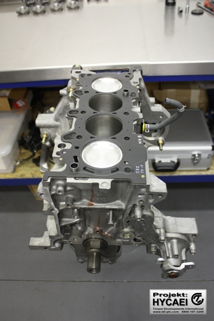
HKS forged pistons and metal head gasket installed
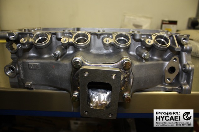
The turbocharger requires an oil drain to the sump so we’ve welded a spigot in as shown below.
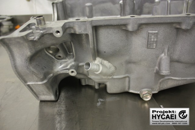
Turbocharger oil drain to sump
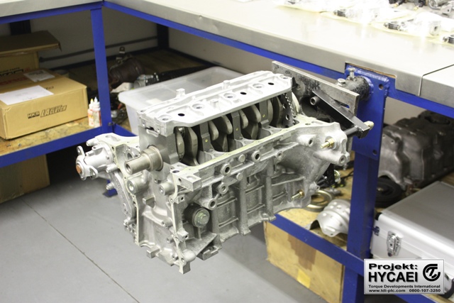
The short engine can now be closed and dressed.
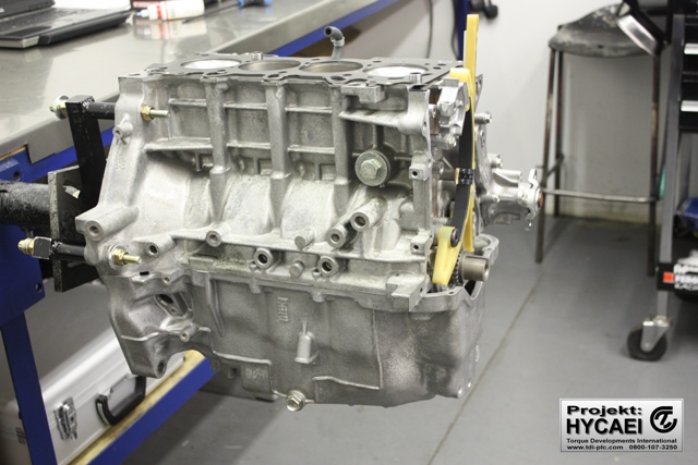
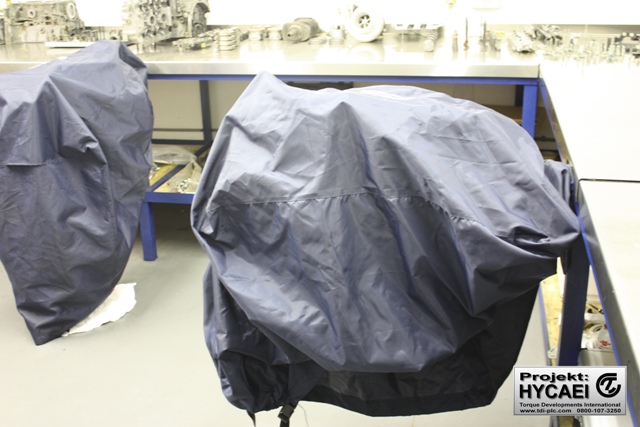
We’ll store the short engine in a clean environment while we turn our minds to the cylinder head…….
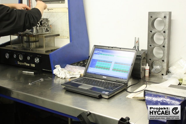
First impressions count, and as soon as we met the CR-Z cylinder head exhaust port configuration we knew we had a challenge on our hands, as the turbocharger relies on drive pressure from the exhaust ports to move the turbine/compressor wheels. We knew we had to maximize the exhaust flow in order to achieve this so we set about making a fixture to conduct air flow tesing on our Superflow flow bench.
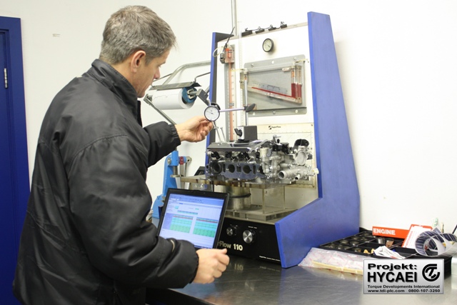
Flow testing the intake ports
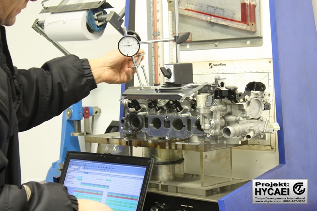
Flow testing the intake ports
Flow testing the exhaust ports
We were able to test the port flow volumes and to map the port velocities to get an understanding of where within the ports were the high pressure areas and the relatively “dead” areas. As expected, the exhaust flow volume was disappointing but at least we know what areas within the ports needed work. Contrary to what some may say is a “black art”, cylinder head porting is actually a precise science that can be applied effectively.
After extensive exhaust port modifications, and lesser work on the intake ports, the cylinder head looked like this:
Cylinder head after modifying the intake and exhaust ports
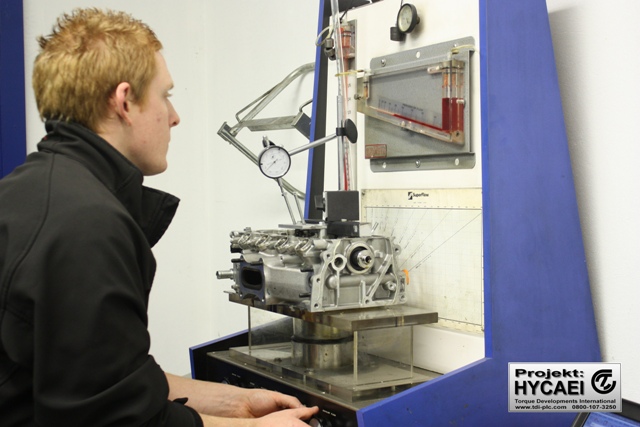
Back on the Superflow test bench we were able to record significant gains in flow volume and velocity on both the intake and exhaust ports
Modified cylinder head back on the flow bench again
Happy with our work on the cylinder head, we use the exhaust manifold flange as a template to design the manifold for the turbocharger then set about making it.
The end result is this turbocharger exhaust manifold:
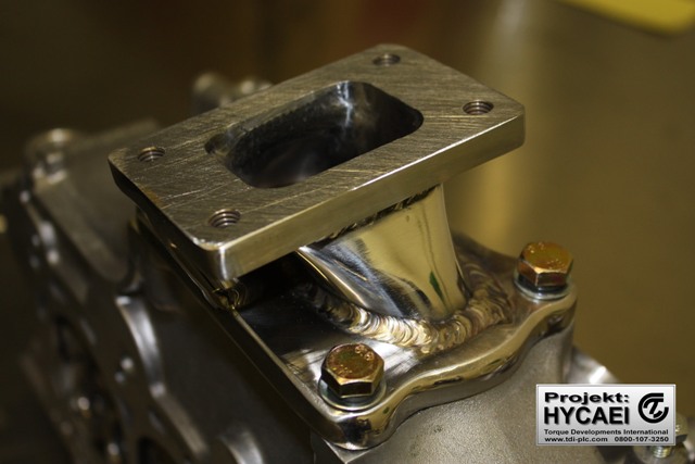
Turbocharger exhaust manifold
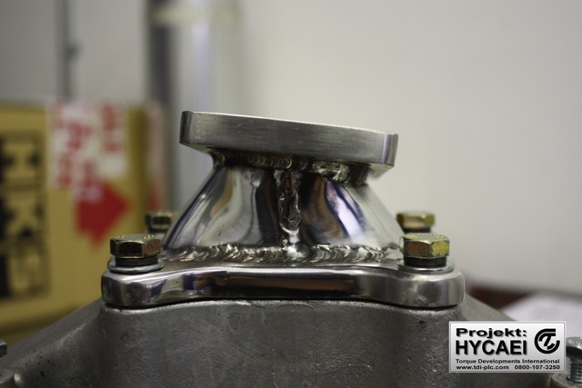
Turbocharger exhaust manifold
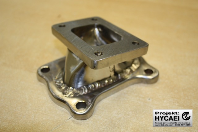
Turbocharger exhaust manifold
Turbocharger exhaust manifold fitted to cylinder head
The next stage of development is to fully assemble the engine!
Engine fully assembled
Engine fully assembled
Re-installing the IMA windings
The standard clutch isn’t capable of holding the anticipated torque output of the turbocharged engine so we used the HKS LA clutch package which comprises a super light flyweel for fast response and uprated organic friction disc and heavy duty cover to provide a relatively soft pedal feel for easy driving.
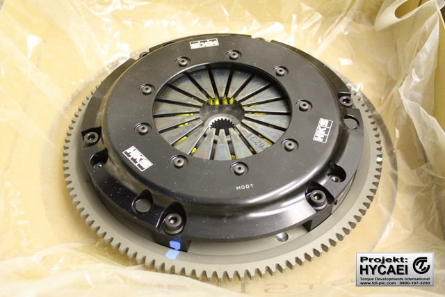
HKS LA clutch kit
The HKS LA clutch kit is installed on the engine will provide good engine response and be nice to drive!
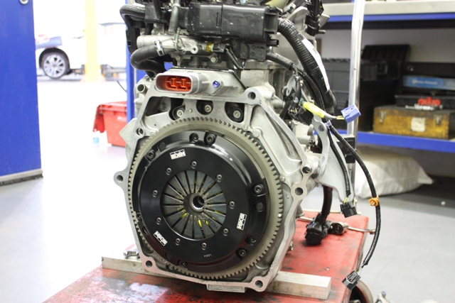
HKS LA clutch kit installed on engine
Just at the right time, Wavetrac announced that they had a limited slip differential available for the CR-Z so we immediately got one in. We’ve had huge success with Wavetrac LSD’s over the years, and many clients state that this is one of the best modifications that they’ve done!
To best understand how the Wavetrac® is truly different from the other gear differentials on the market, you first have to understand the primary problem that the Wavetrac® solves. Zero axle-load is a condition that occurs during normal driving, but creates the most noticeable problems when driving in extreme conditions. Zero or near-zero axle-load is the condition that exists when there is ‘no-load’ applied through the drivetrain, when one drive wheel is nearly or completely lifted (often in aggressive cornering). It also occurs during the transition from engine driving a vehicle to engine braking and back, even with both drive wheels firmly on the ground.
The innovative, patent-pending, Wavetrac® device in the center of the diff responds during these exact conditions when zero or near-zero axle-load occurs. At or near zero axle-load, the axles (and therefore each side gear in the diff) start to turn at different speeds. This speed differential causes the Wavetrac® device to step into action: Precisely engineered wave profiles are placed on one side gear and its mating preload hub. As the two side gears rotate relative to each other, each wave surface climbs the other, causing them to move apart. Very quickly, this creates enough internal load within the Wavetrac® to STOP the zero axle-load condition. The zero axle-load condition is halted, and the drive torque is applied to the wheel on the ground (the gripping wheel)… keeping the power down. Some gear differentials rely solely on preload springs to combat loss of drive. The drawback is that you can’t add enough preload to prevent loss of drive without creating tremendous handling and wear problems at the same time. So, to avoid these problems, the preload from ordinary spring packs must be reduced to a level that renders them ineffective at preventing loss of drive.
The Wavetrac® is the only differential that can automatically add more load internally when it’s required. In the case where both wheels are on the ground during zero axle load, such as during a transition to deceleration, the Wavetrac® device is able to prepare the drivetrain for when the zero torque condition stops, eliminating the delay seen with ordinary gear diffs. What this means for you as a driver is that power is delivered to the gripping wheels for more time and in a more constant manner – making you faster and improving stability. The Wavetrac® truly is different – and its innovative features can make a real difference in your car’s performance.
Here are more features that make Wavetrac® even better: The new Wavetrac® Differential brings current gear technology to the market. Internally, its gear tooth forms are optimized for strength and improved oil film retention over competitive designs. The gear package is smaller, reducing overall mass, yet is more durable since particular attention was paid to the tooth strength – optimized for high torque conditions. Attention was also paid to the side gear/axle interface, putting as much material thickness as possible in this critical area – most important when power levels get high. If you appreciate quality, you’ll appreciate Wavetrac®. You can see it, feel it. The Wavetrac® is not just good on paper. They’re build them to last: • High strength 9310 steel gears • Case hardened, billet or forged steel housings • ARP® fasteners throughout.
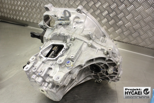
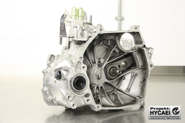
Here’s the CR-Z transmission prior to disassembly:
The transmission cases is split to expose the internal gears and standard open differential.
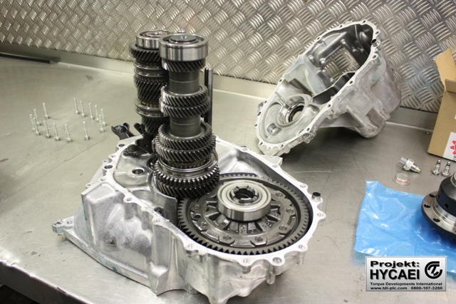
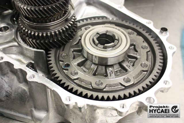
the standard differential is an open design
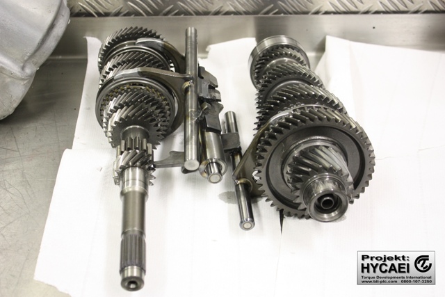
Transmission gears, shafts and selectors
Here’s the legendary Wavtrac limited spli differential just removed from it’s box:
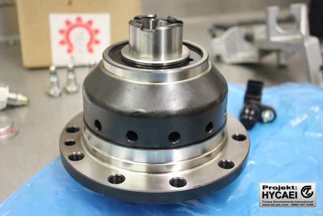
Wavetrac limited slipp differential
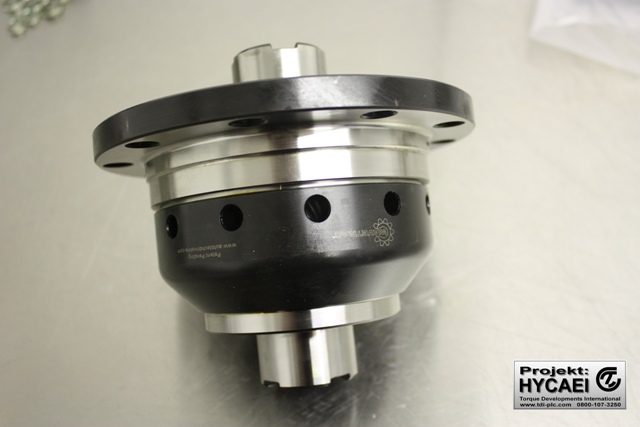
Wavtrac limited slip differential
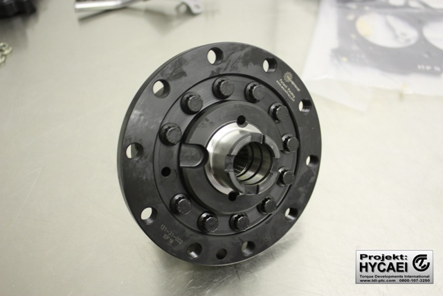
wavtrac limited slip differential
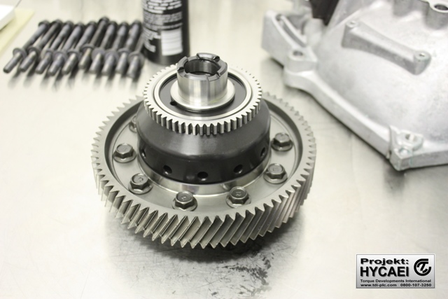
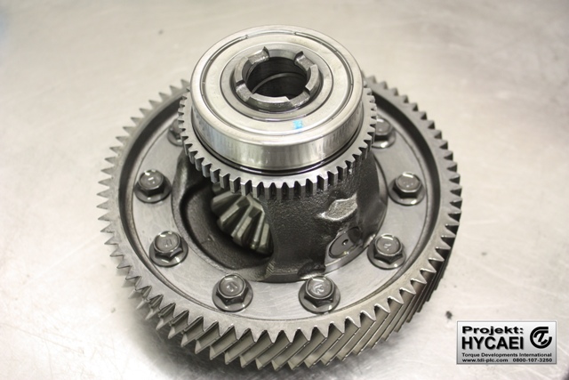
Wavetrac fitted with crown wheel
The Wavetrac installs in exactly the same way as the OEM differential, so we follow Honda’s instructions.
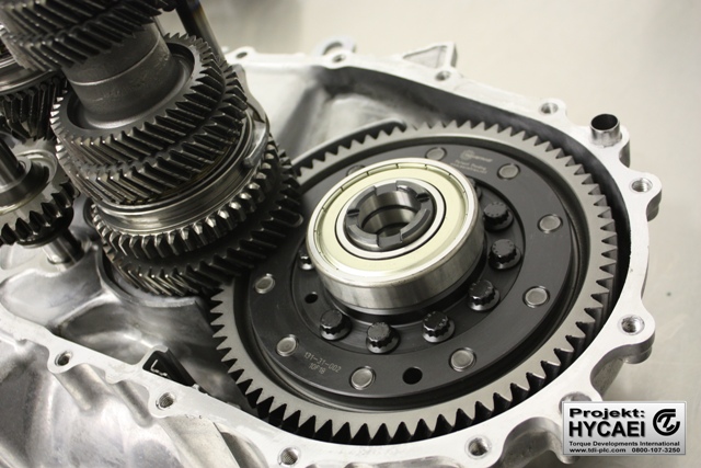
Wavtrac installed
The transmission is reassembled and she’s good to go!
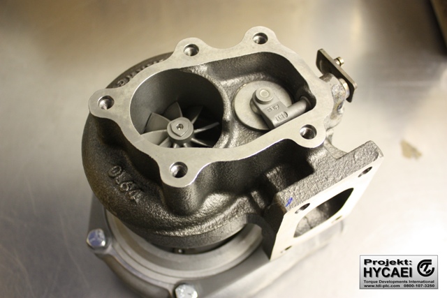
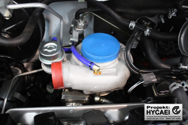
Turbocharger sizing and development is a core competancy of ours, so designing the specification of this turbocharger to match the objectives and airflow characteristics of the engine is a process that we relish. We settled on a custom built Garret GT turbine which features a ball bearing cartridge, with specific anti-surge ported shroud compressor housing, compressor wheel and turbine housing.
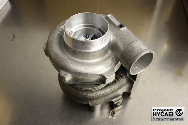
Garret GT turbine
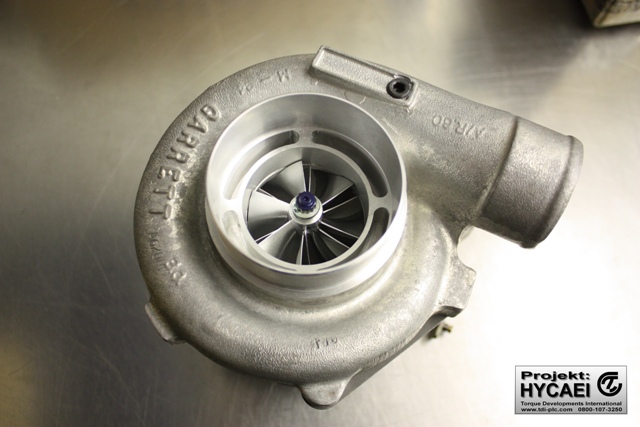
Here’s the ported shroud compressor housing that reduces compressor surge
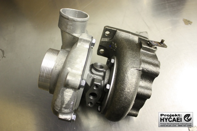
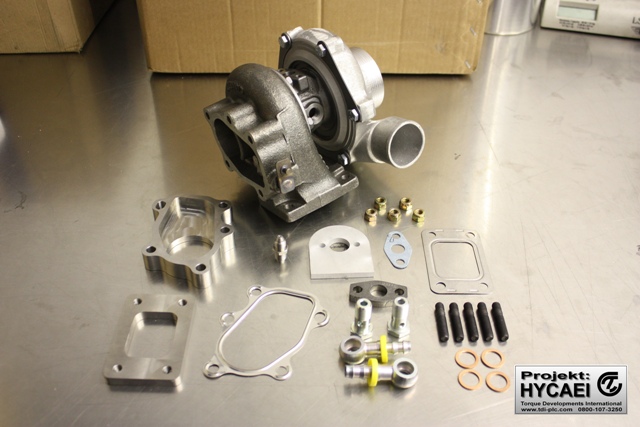
Here are the associated components necessary to install the turbocharger.
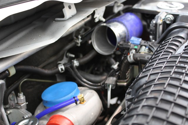
Now that the engine is fitted in the chassis we begin to figure out the pipework for the air filter box > turbocharger intake > turbocharger compressor > intercooler > throttle body, and of course the exhaust downpipe and hydraulic lines.
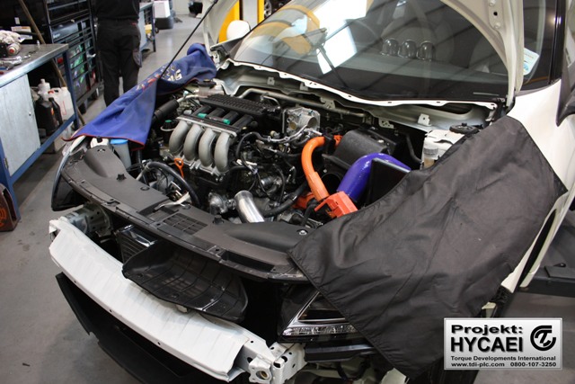
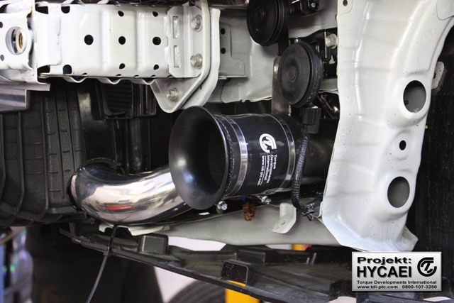
Due to packaging constraints, we’ve come with a turbocharger mounting strategy that’s somewhat unorthodox which you may find interesting. We’ve mounted the turbocharger vertically!
“Stacked” turbocharger
Some time ago we invented a way to improve the aerodynamic efficiency of intercooler cores. We use a special core end plate that reduces the internal flow restriction to reduce the pressure drop across the intercooler. The positive effect is that there’s more boost pressure seen at the plenum. We branded this design as “Katana”.
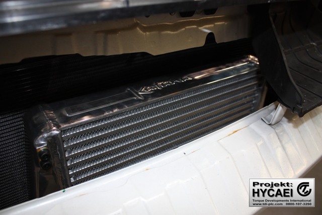
Katana intercooler
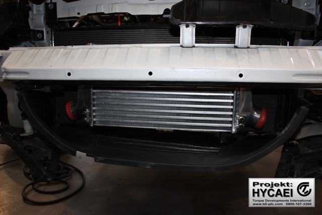
Katana front mounted intercooler mounted to CR-Z
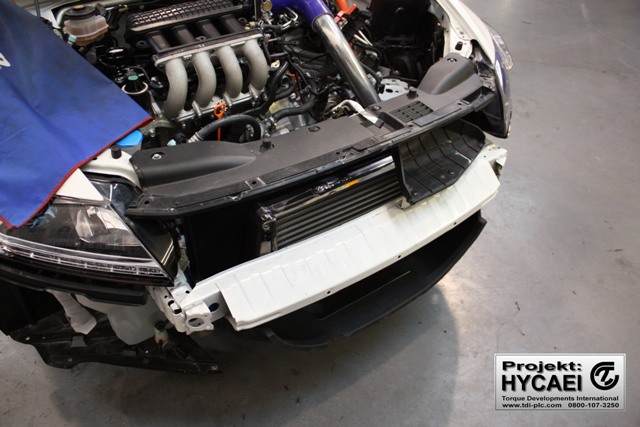
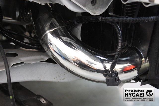
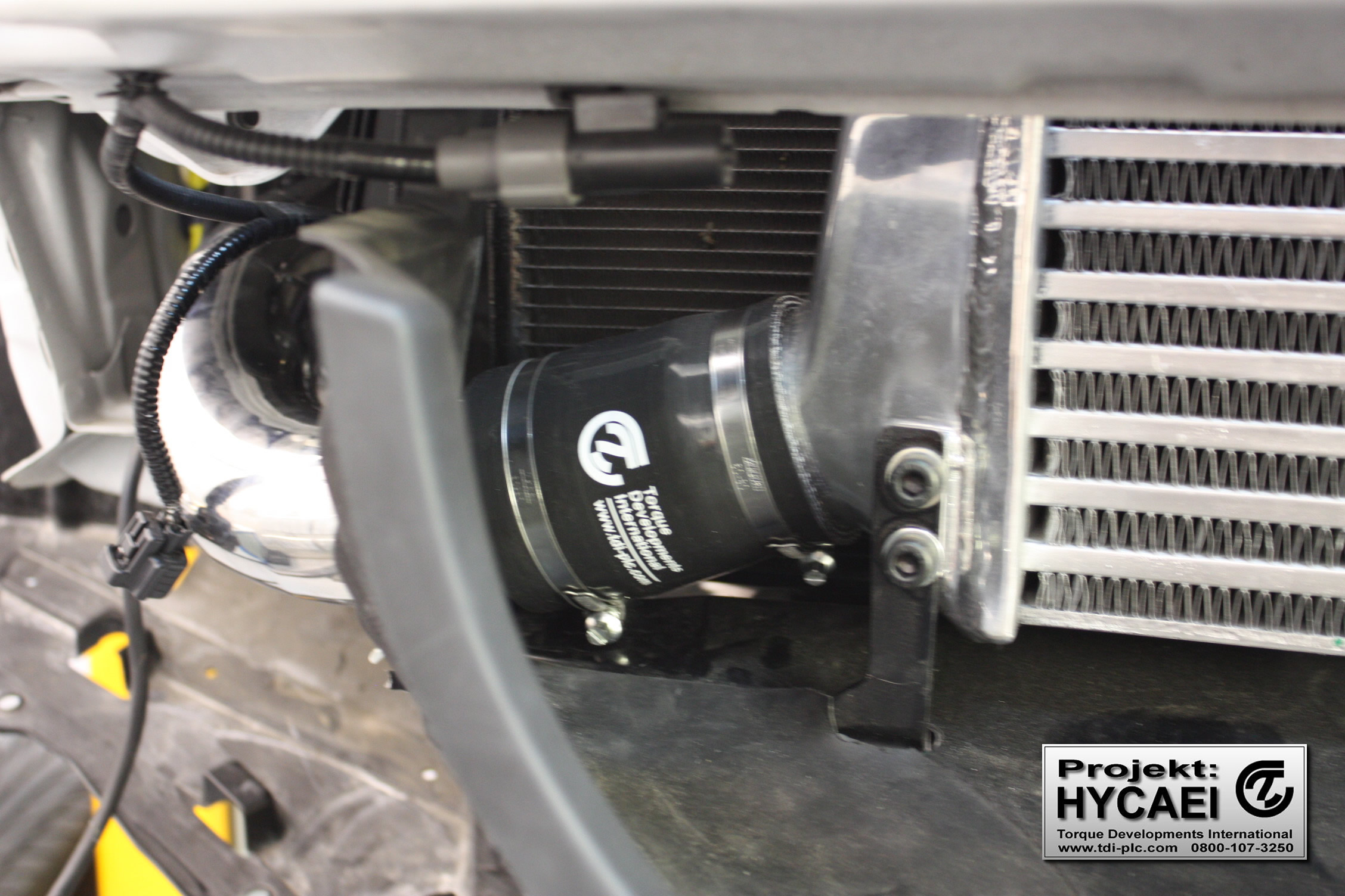
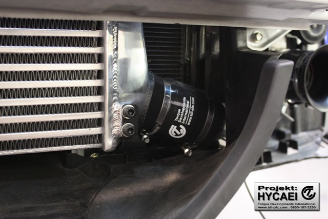
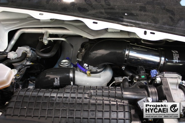
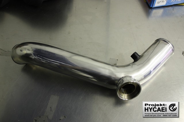
Pipework for compressor housing intake and discharge.
we’ve used a velocity stack in a high pressure location in the front bumper which feeds the Mugen air box.
Velocity stack
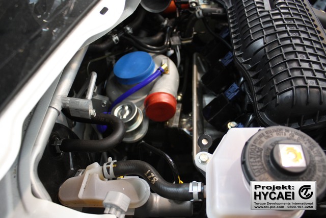
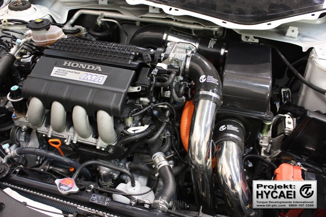
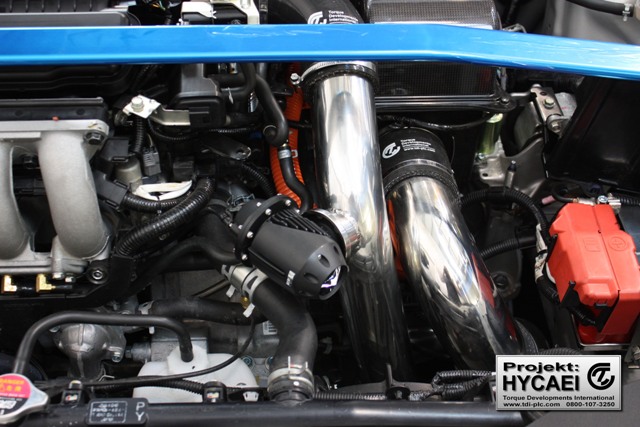
We’re very pleased with the outcome of the turbocharger pipework!
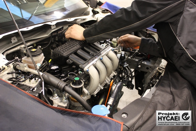
To keep things relatively simple we decided to start the new engine using the standard fuel injectors, inlet manifold and throttle body. With the engine now successfully running (and sounding absolutley great!) we installed larger fuel injectors and the manifold and plenum from the Honda FIT
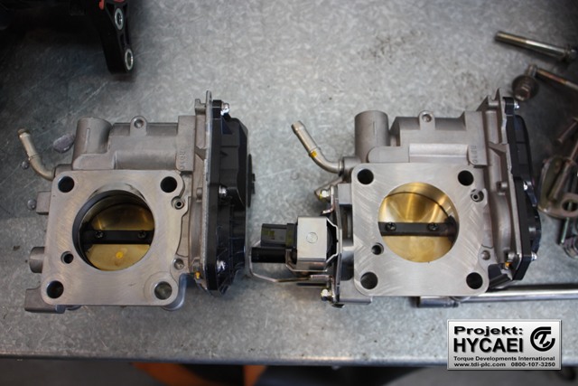
CR-Z throttle body on the left, FIT on the right.
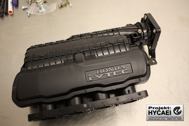
Honda FIT inlet manifold
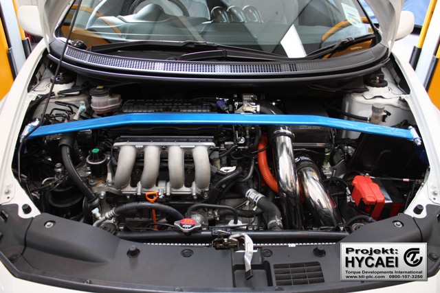
The Honda FIT intake manifold, plenum and larger fuel injectors are not installed, accompanied by a Cusco strut brace.
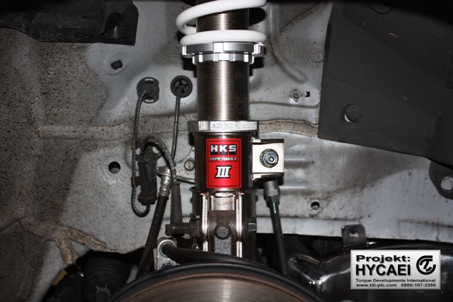
The engine has been freshly built with HKS connecting rods and pistons so has to be run in for a while before it can be tuned properly. In the meantime, were’re installing an HKS Hipermx 3 suspension kit which features adjustable ride height and damping so that we can optimise the handling.
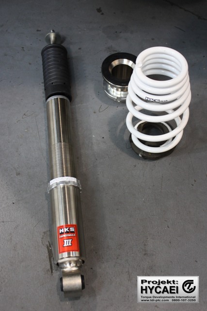
Hipermax 3 rear shock, spring and adjustable platform
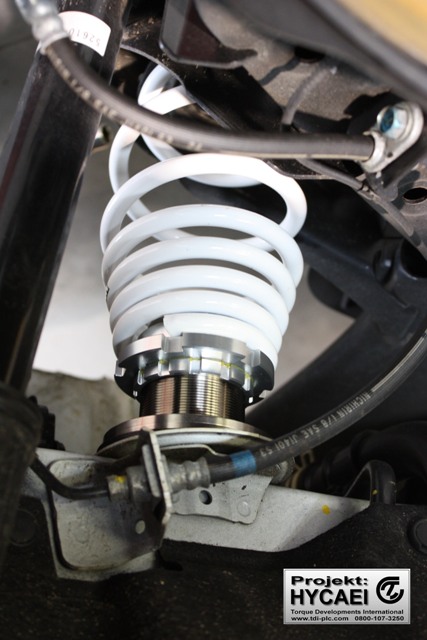
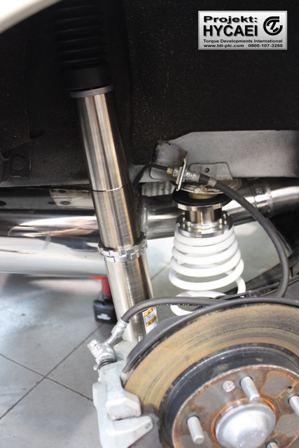
Hipermax 3 rear spring and adjustable platform installed
Hipermax 3 front strut installed
Hipermax 3 rear shock, spring and adjustable platform installed
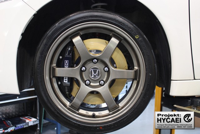
It would be unwise to have such a significant improvement in dynamic performance without improving the braking capability so we installed a Stoptech big front brake kit.
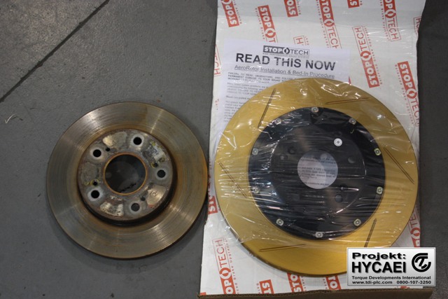
Standard disc on the left, Stoptech on the right
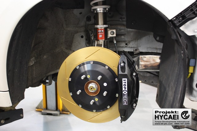
Stoptech big front brake kit installed
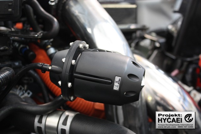
We’re using a blow off valve to dump the pressurised air on throttle closure. We welded a stainless steel flange to the intake pipe.
HKS SQV flange welded to intake pipe
We use the HKS SSQV because it’s the most reliable on the market
The final installation is neat and tidy!
Today we’re building a running in map for the engine so that it has a few miles under it’s belt before we tune it for full power.
Today we’ve completed the geometry calibration and suspension set-up for our stage 3 FRS upgrade which incorprorated the HKS coil-over suspension kit. We do also offer other brands of suspension kits too.
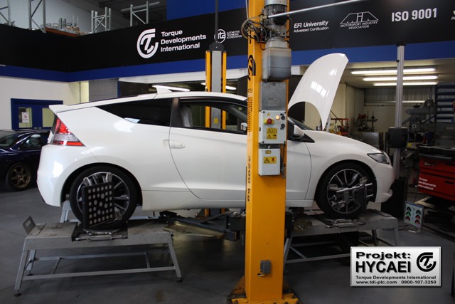
Turbocharged CR-Z on geo rig
Quite understandably, there seems to a fair amount of confusion over chassis dynamics in general and specifically about geometry optimisation which is often refered to as “FRS” being an acronym for Fast Road Setting. We attempted to dispell the myths by authoring this document on the subject:
What is a “Fast Road Geometry Set-up”? The term fast road set-up is one which is frequently banded about amongst car enthusiasts but let’s look at what it actually means. Well firstly the term doesn’t have one single meaning, it’s a term used normally by tuning companies to summarise a group of adjustments and/or upgrades that improve a cars characteristics for performance orientated driving but mostly it’s used to describe changes to a cars suspension system. The key point here is that not all fast road set-up’s (FRS’s) are the same and they are certainly not all equal, an FRS is normally just one persons opinion on what is required to improve a car towards performance use, some of these engineer’s base this work on a solid understanding of the sciences involved and a wealth of direct experience, others however do not have these assets and have to just rely on good old trial and error to find something that in their opinion works. For the enthusiast looking to improve the performance of their car it’s important to understand what’s on offer so that they can be sure that they are getting good value for money from the companies involved and also so that they can choose a service that is right for them personally. So the average fast road set-up can vary from simply revised settings for the standard suspension set-up all the way up to complete replacement of the entire suspension hardware, adjustment of the cars ride heights and geometry positions.
Who decides the FRS geometry and how? To understand how the wheel geometry effects vehicle dynamics at large it is unfortunately necessary to understand in depth how a pneumatic tyre works in the way it communicates forces to and from a wheel rim and also the physical mechanisms which allow the tyre to generate the grip in the contact patch which is necessary to actually create those forces. The key point to get across here is that at the FRS level we’re not looking to re-invent the wheel by starting from scratch with the chassis dynamics rather we’re looking to tweak what is there with a view to biasing the handling traits in the direction that we require. The best method I find is to first start with a problem, or perhaps a list of problems before we start looking for any solutions.
The basic method we use here at Torque Developments looks like this; 1. Speak to the drivers of the cars in question and look for common points of agreement as to the negative aspect of the cars handling 2. Test drive the car ourselves blind before any other technical investigation is carried out, this helps us formulate our own opinions on the chassis behaviour and serves to act as a baseline for future road tests 3. Measure the static chassis geometry (Camber, Caster, Toe) 4. Measure the basic dimensions of the chassis (Wheel bases, axle widths, axle centres and stagger) 5. Measure the kinematic geometry (Toe and Camber gain curves, Ackermann, Scrub Radius and SAI) 6. Measure force generation data from the chassis in a live driving environment via on-board high speed data logging. 7. At this point armed with all of this technical knowledge of the chassis plus the list of complaints and information gained during our own test drive we look at all of the evidence and search for potential causes of our problems 8. After hopefully identifying problematic areas of the set-up at least areas of clear compromise, we then look to make some small adjustments in these key areas and then test to witness the effects 9. If the effects are seen to be nicely in line with our expectation then we can begin zeroing in on the final set-up small steps at a time 10. Once we’ve biased the handling towards our goals and taken care of any negative traits, we then set about final testing the set-up which involves higher mileages and more extreme environments in order to bring any unwanted side effects to the foreground. As long as no ill effects of our modifications are found we then sign off the fast road set-up and offer it to the customers for feedback, only when both the customer and ourselves are happy with the set-up will we then offer the setup to other owners the same model of car. Even once we have arrived at a known good FRS we still alter each FRS to best suit the needs and wants of the specific customer in question and every single car is test driven to make sure it is performing exactly as expected before being signed off and handed back to the owner.
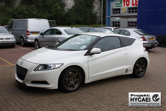
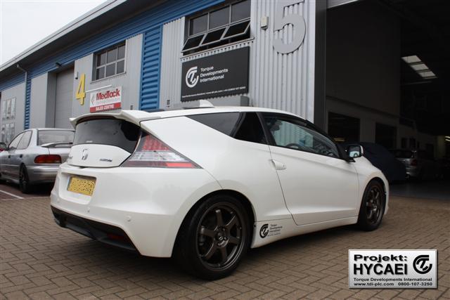
The CR-Z is looking a million dollars with it’s new wheels and tyres! We’ve gone for 17 x 7.5J Rota Grids in bronze with Yokohama Prada Spec II 215/40/17 tyres.
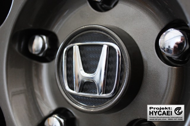
Original Honda centre caps were specific to the OEM wheels, but with a little bit of clever thinking, The OEM logo was transferred onto the Rota centre cap with a carbon backing to finish it off.