Mustang 4.6 Modular Forged Engine
Here’s our story about rebuilding a Mustang 4.6 litre 3 valve engine using uprated forged internal components which are much stronger than the original Ford counterparts. For those wishing to “cut to the chase” and find out where to get these components, there is a link at the bottom of this page.
Firstly a bit of preamble about this engine. The 4.6 Modular engine was produced in 2, 3, and 4 valve variants which were available for 5 years between 2005 and 2010. Full information on these and the other capacity Modular engines can be seen here.
Whilst mostly reliable in standard form, the 3 valve engine suffers from weak connecting rods which can break when the power in increased. Connecting rod failure is potentially catastrophic as it will normally put a hole in the cylinder block, often damages the crankshaft, and sometimes one of the cylinder heads will also become wounded by coming into a piston traveling at high speed. We’ve seen plenty of these fails! If any significant performance increase is anticipated the connecting rods should be replaced with stronger forged steel components which will ensure a trouble-free performance. Whilst the engine is apart there are other precautionary and/or upgrade modifications that can be done at the same time.
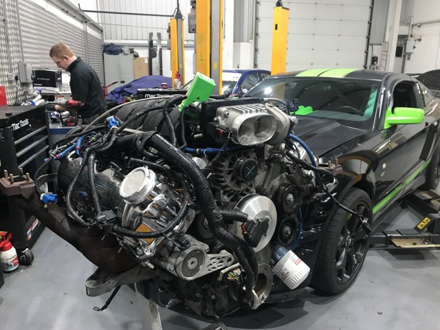
The Mustang we’re focusing on here has been fitted with a twin turbocharger system, and the owner is expecting close to a 4 figure power output so there is no chance whatsoever that the standard engine will cope with that or anywhere near it!
Fortunately, the owner of this car took the wise decision to upgrade the engine prior to it (inevitably) failing, which removes the cost of replacing consequentially damaged items such as crankshaft, cylinder block, cylinder heads etc. A very sensible choice indeed!
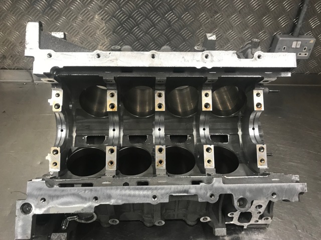
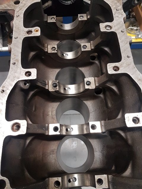
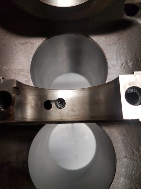
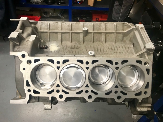
One of the modifications that we always recommend for any engine that is making the transition from natural aspiration to forced induction (turbocharged or supercharged) is to add piston oil squirter jets (if they’re not already fitted). This also applied to older generation forced induction engines that don’t have piston oil squirter jets. The purpose of the jets is to direct oil from the main pressure gallery into the underside of the pistons, which has the two-fold piston cooling advantages of making the pistons more reliable (due to less thermal loading), and being able to have a higher MBT ignition point giving a better performance or a wider knock limit for engine safety. We use a special spring-loaded one-way valve machined into the cylinder block for this purpose. It’s quite a tricky operation but well worth the effort. We can undertake this process on most types of cylinder blocks. The images below show the standard cylinder block, and another block (not Mustang) with the machining process and jet installed into the main bearing tunnels (one per cylinder). This is a fantastic little upgrade!
Here are some photos of the standard cylinder block (on the left), and a modified block (not Mustang) with the oil squirters fitted:
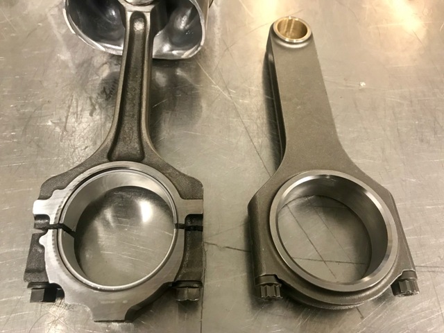
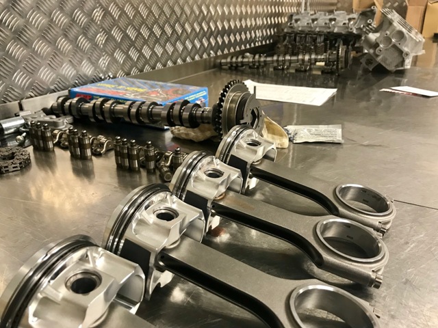
As we already know, the connecting rods are very weak so should be upgraded. There are various types and brands available, and like most things in life – you get what you pay for! They are generally split into two types; H Section and I Beam. As per the photo below the original rods (on the left) are I beam style, and the uprated H beam rod we’ve selected is on the right. You can see how much thinner the original rod is! Very often the original rods are manufactured using a casting process, whereas uprated rods are manufactured from a forged steel (normally EN40B) billet which is much stronger, so we’re benefiting from a superior design and more robust material. Additionally, they come with high tensile ARP bolts which are better able to withstand the increased stresses of high power – high RPM engines. Please note that using connecting rods having a different weight to the original has a significant impact on the rotating balance. Here’s a photo of the standard connecting rod on the left and an H section forged steel uprated version on the right:
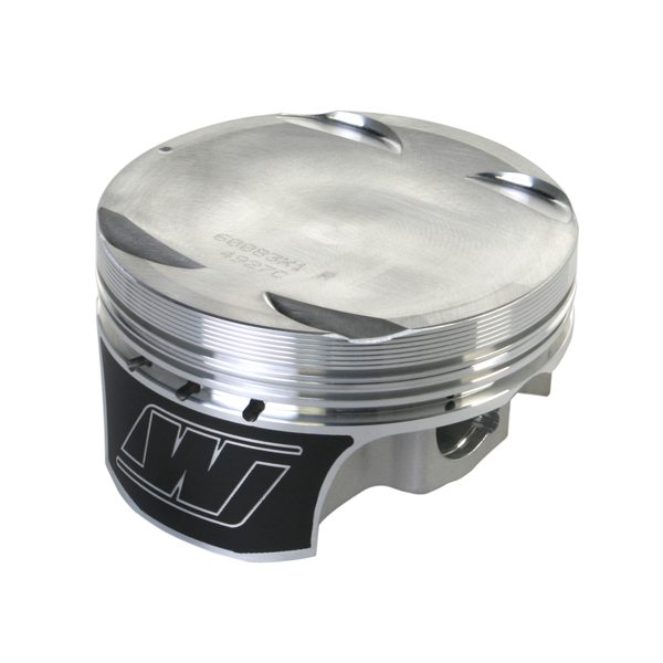
At this point we have the option of either retaining the OEM pistons or using heavy-duty forged alternatives. Because this is engine going from natural aspiration to forced induction, the original compression ratio isn’t ideal so we’re installing lower compression forged pistons for strength, reliability and performance. Again, there are plenty of options of brands, designs, compression rations etc. We’re using Wiseco pistons for this application, with Xylan anti-friction coatings. Please note that using pistons having a different weight to the original also has a significant impact on the rotating balance. The photo below is a Wiseco forged piston with Xylan anti-friction skirt coating:
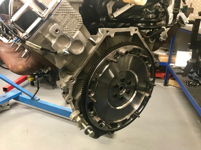
Engine balancing is something that should be done at this point. Most modern European and Japanese engines have a balance tolerance of around 3 grams, but US engines are often over 5 grams, so not ideal! Many balancing shops use 2 grams as tolerance, but we like to target less than 1 gram. It takes a bit more time and effort to do but is well worth the effort. Any imbalance is a parasitic kinetic loss that should be transferred to useful kinetic energy at the wheels, and imbalances increase the rate of main bearings wear. V8 engines require more effort to balance than in-line engines because the weight on the reciprocating components needs to be measured/calculated/emulated for the process. Here’s a video of this engine with the clutch being balanced. Here’s another video of just the crankshaft being balanced. We statically balance the pistons and rods to within 1 gram, then we individually dynamically balance (in this sequence) the crankshaft, front pulley, flywheel, then clutch cover, so that should the clutch, flywheel, or front pulley need replacing at any time in the future it can be done without affecting the crankshaft balance.
One of the biggest mistakes that people building engines make is that they don’t check the clearances. The assumption is made that the machine shop has done the job properly. To give you an idea of the problem, at least 50% of the machining work that we sub-contract out such as crankshaft grinding and cylinder block boring, does not pass our ISO 9001 QA process so gets rejected. If you don’t check the clearances you won’t know about the defect/s!
Another big mistake we see is a lack of cleanliness. The engine building environment must be spotlessly clean, otherwise, even the smallest piece of dirt or debris can have an avalanche effect as creates more debris as it travels around the engine.
The first thing we check after cylinder boring is that the size we requested is actually correct. Often it’s not! We specify the precise size we want taking into account the size of the piston and the clearance required. We don’t always use the piston manufacturer’s suggested clearance as they are often sub-optimal. Then we check for ovality and taper which can happen if the boring process is done too quickly.
Another mistake that we see quite regularly is the assumption that the piston ring gaps are correct out of the box. This is rarely the case so the gaps should be set by modifying the rings.
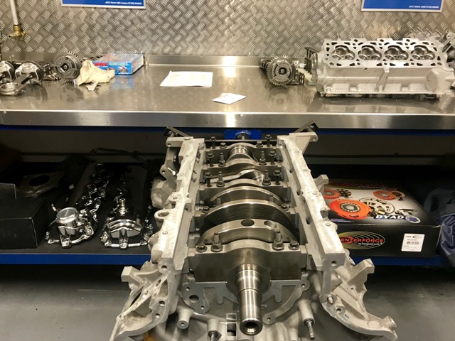
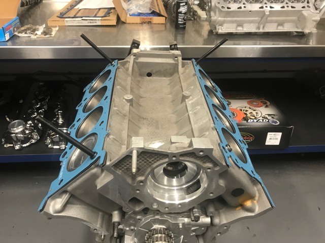
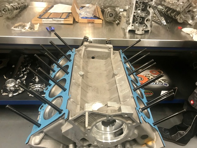
After carefully checking the main-bearing and thrust clearances, the crankshaft is installed into the cylinder block and torqued to the correct setting.
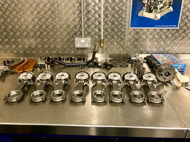
The piston rings are fitted to the pistons, the pistons are fitted to the connecting rods, then the whole assembly is fitted to the cylinder block. Remember to check the connecting rod bearing clearances and modify them if necessary!
When the cylinder block is assembled, we normally recommend using heavy-duty ARP studs and bolts, etc wherever possible in order to withstand the harsher conditions.
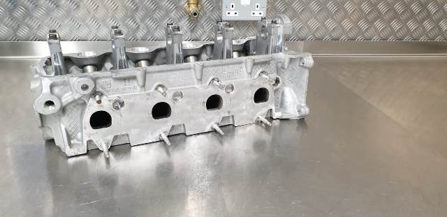
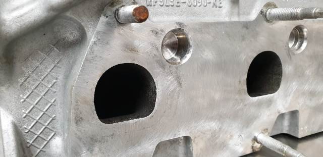
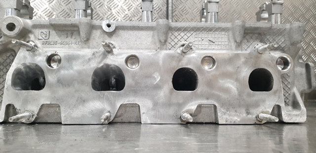
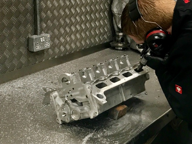
Next in our Mustang forged engine build process, we move on to the cylinder heads. In this case, the valve guides were worn so have been replaced, but more importantly and interestingly the heads will be ported to improve performance, which is a specialty of ours. With forced induction engines the intake port runner sizes are often adequate so don’t need enlarging but we do pay careful attention to the valve throat and seat areas to improve the internal aerodynamics. The majority of the effort should be concentrated on the exhaust ports as the intake volume will be at least 50% greater so any restrictions in the exhaust will reduce performance. In the photos below you see the shape and size of the original exhaust ports compared to the optimized ports. The 4th photo shows 2 modified ports and 2 standard ports. Quite a difference!
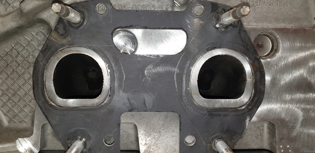
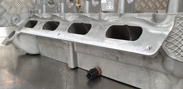
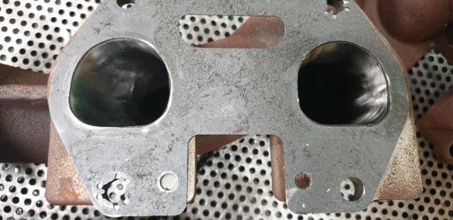
Whilst enlarging the cylinder head exhaust ports it’s a good idea to match the manifold ports at the same time. Remember that any back-pressure in the exhaust reduces performance. The photos show the standard manifold on the left and modified version on the right:

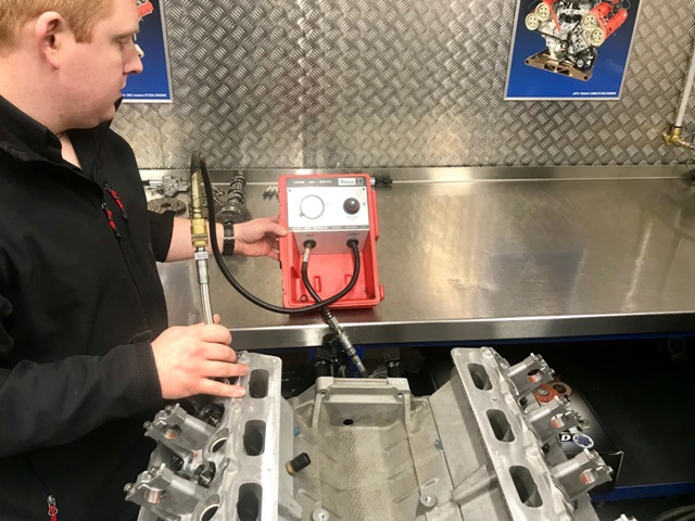
With the heads ported, the valves are seated, springs are fitted, camshafts installed, then fitted to the cylinder block. It’s always sensible to check the cylinder leakage at this point so that any issues can be dealt with before the engine is back in the car!
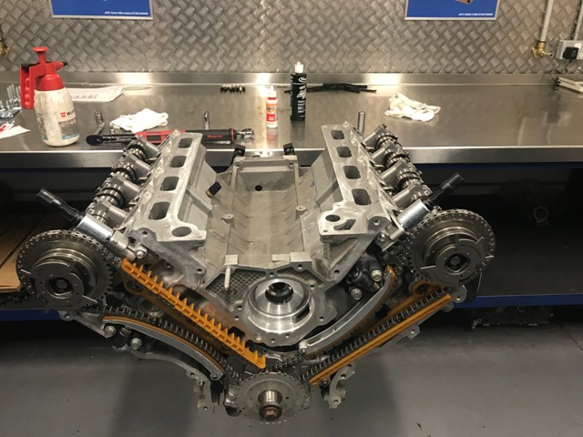
The camshafts are timed, and the remaining components of the engine are installed.
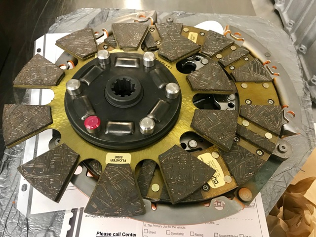
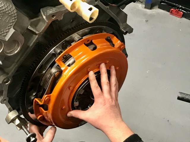
There are plenty of uprated clutch and flywheel kits available, but we really like the Centreforce DYAD kits because although they are multi-plate they have an anti-rattle feature to keep it quiet, a dual-friction lining that is not as harsh to use as cerametalic linings, and a centrifugal weigh system on the clutch cover that increases clamping pressure as revs rise. It drives pretty much like a standard clutch but holds much more torque:
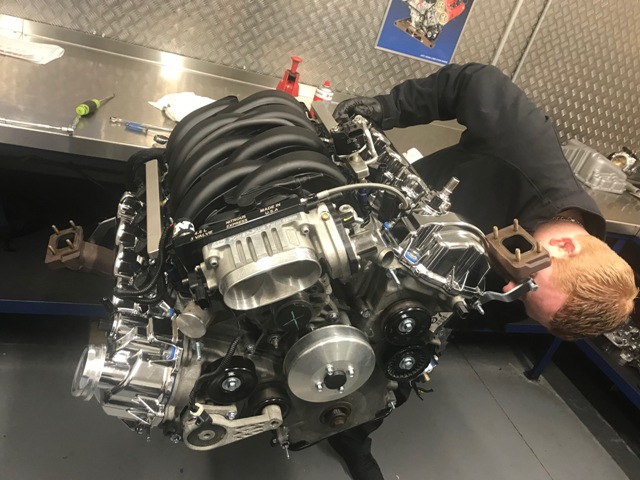
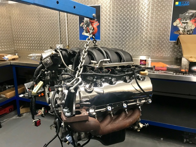
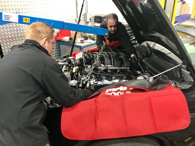
Here’ the engine being refitted into the car:
We are really pleased with the outcome. Here’s a video of how smooth the engine runs even with wild camshafts fitted:
Please contact us for your engine building requirements.
Mustang 4.6 Modular Forged Engine build components and options can be seen here.